ESUMS RWDC
Systems Design
2. Document the System Design
2.1 Mission Design
The UAV designs were initially based on the three minimum requirement missions to ensure that all necessary components were included. The additional missions were then designed to optimize the use of these components within the criteria and constraints of the RWDC and FAA guidelines. By designing the UAV first, the team ensured that they had already formulated a UAS that could accomplish the goals with the given constraints. The team determined that it was not necessary to have every detail of the missions planned out prior to the design, provided that the design could meet all criteria and constraints specified in the Real World Design Challenge’s Detailed Background document. This also gave the team more creative freedom, as they could base missions off of aspects of the design that were created for cost-effectiveness, weight efficiency and flight stability; as long as doing so did not change the UAV’s ability to meet the initial constraints.
The first minimum-requirement mission, the logistics mission, has the highest payload requirement of the three required missions, with a mandated weight of eight pounds. The purpose of this mission is to transport a single large tool to the farmer in a part of the field located a maximum of 1 mile away from the UAV’s starting point. The purpose of the tool and its delivery to the farmer is variable but can range from hammer, screwdriver or wrench requiring repairs to field specific agricultural technologies such as field monitoring devices. This mission’s capability will allow farmers to save time and money by addressing immediate needs maintenance which might have proven costly if left without immediate care. For example, if the farmer travels out to their field to diagnose a problem with their irrigation system, they might discover that the problem requires a toolbox or that they brought the incorrect tool to the site. Rather than traveling back to the location of the tool, which allots more time for the problem to continue, they would then request that an operator send the UAV to the farmer’s location with the necessary tool(s), saving the farmer the time and fuel expenditure of a two-mile round trip.
The second minimum-requirement mission, the survey mission, had no payload weight requirement other than its camera and an additional multispectral sensor. The cost analysis indicated that the improved functionality and marketability provided by the sensors would justify a slightly increased system cost. The UAV uses this multispectral sensor to detect moisture in crops which saves farmers money by increasing crop yield, generating more food and food products per unit of work and resources expended. The moisture detection function is accomplished using thermal and infrared imaging, which enables the camera to collect data that can be translated into moisture content by comparing thermal values with a baseline moisture level. Farmers benefit from using such a system, as droughts are expected to increase in future years due to climate change, placing additional strain on irrigation systems. Effective data-driven moisture detection will also allow farmers to use water more efficiently by delivering it only where it is needed, and conserving the remainder of its resource.
The last minimum-requirement mission, the dash mission, requires that the UAV be capable of transporting a payload of two lbs to a location 1.5 miles away, traveling as fast as possible, while not breaking the FAA maximum speed limit of 100 mph. The purpose of this mission is to help protect farms from unpredictable weather-induced damage by monitoring atmospheric conditions. In many parts of the United States, weather can create unforeseen conditions such as: frost, humidity changes, strong winds and cold fronts, which can be detrimental to crops, livestock, and infrastructure. The UAV will carry a payload consisting of sensors that record air pressure, temperature, humidity, and wind speed to detect large scale and localized weather patterns throughout the field. For example, the farmer might use the drone to measure whether or not frost is forming earlier in the harvest season, or even decide how wind speed would affect the spread of pesticides. Longer term applications include monitoring seasonal humidity changes to better predict how water should be allotted to different crops. This not only provides valuable scientific data for the region, but also allows farmers to take action before an unpredicted change in weather or atmospheric conditions negatively affects their crops. This scenario is ideally suited to the dash mission, as the sensors in the payload component selection identified for this task are well within the weight requirements, and weather data must be transferred in an expedient manner in order to be timely and accurate.
In addition to the three minimum-requirement missions, the team decided to create three additional missions to improve the business case of the UAS and maximize the objective function. The first of these additional missions involves the use of real-time image analysis and GPS or Bluetooth locator tags to monitor livestock movements. The UAV would stay airborne for approximately 40 minutes while it surveys a livestock grazing area based on coordinates specified by the farmer and/or remote operation. It will ensure that individual animals do not stray too far from predetermined waypoints by alerting farm personnel in the case of such an occurrence. This could save time and resources, as the drone could keep livestock in a set location for up to 40 minutes, so that the farmer is less likely to lose livestock and does not have to employ individuals to watch the animals constantly (Villiers, 2015).
The second additional mission involves an extended survey of the land, processed by a high-resolution camera for eventual 3D imaging. Using the payload camera, the UAV will capture the data of a structure or landscape while orbiting in a pattern that generates a multitude of images from many angles for later processing and image-stitching. This information can then be uploaded to a computer interface with image-stitch software, where the data can be processed into a point-cloud model of the object. With a single reference distance, this allows farmers to accurately measure the dimensions of their fields in order to comply with zoning laws for new construction or to obtain a visualization of their fields for improving irrigation and sustainability. The 3D imaging function could also be used to explore new lands for farming in rocky terrain, expanding the possibilities of agriculture to previously non-arable land and increasing global food production.
The third and final additional mission is a variation of the logistics and dash mission, but includes specific scientific equipment for more precise sensor readings and tool transport. The UAV will be able to transport small sample containers to a location in the field at least one mile away and return with the full sample containers without refueling or recharging. The samples must be filled by a farmer or operator in the field, but can contain water from irrigation systems, soils, fertilizers, captured insects, and/or sampled parts of plants. These can then be returned to the mission site and transported to a third-party for analysis and bioassessment. The team’s company will also provide these services for an additional fee. The analysis results can be a critical component of adaptive management and responsiveness to changing environmental conditions for the farm, as soil conditions and water quality should be evaluated frequently to account for any problems or contamination that might arise.
2.2 Conceptual, Preliminary, and Detailed Design
2.2.1 Engineering Design Process
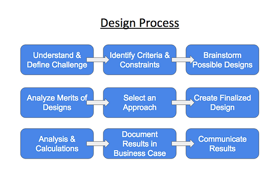
Throughout this project, the team chose to follow the nine-step engineering design process (Figure 2.2.1a) adapted from the general outline that the team followed during last-year’s project. Last year’s process was fairly successful overall, but this year’s version still implemented improvements in several areas, particularly emphasizing the conceptual design phase and setting more stringent documentation requirements. This was a modified version of the twelve-step engineering design process frequently used in high school Project Lead-the-Way engineering courses (Figure 2.2.1b). The steps are a chronologically organized approach to completing all the necessary parts of an engineering project. From defining the problem that the team is working to solve, to conducting research and analysis, to communicating the final results of a design proposal, this process typically allows teams of engineers to complete projects in a timely, effective, and organized manner. While this process can be shortened to as few as five steps, the team determined from prior academic experience that the nine-step design process would be most suitable for completing this project. Other processes, which are shorter in length and level of detail, could potentially address the necessary requirements needed for the conception of a design. However, they are not fitting for an in-depth project, as more detail within each step is required in order for elements of the design process to align well with the many components of the Challenge.
For example, in the five step design process, the basic steps are given in a broad form: define the problem, brainstorm solutions, make a model, test the model, reflect and redesign. Although these steps can lead to the completion of a final product, using this process will often lead to creating more substeps for the team to follow in order for one full step to be complete. The creation of substeps for each of the five larger steps will often require more time and adjustment than using a previously expanded engineering process. Therefore, the team has decided to use the expanded nine-step version, because it provides greater detail and more closely aligns with the constraints of the Challenge project.
Figure 2.2.1a. ESUMS Aviators Design Process.
Figure 2.2.1b. Project-Lead-the-Way engineering design process. Reprinted from Curriculum, Instruction, and Assessment (page 1), by Neshaminy School District (2007).
While the twelve step engineering and design process provides the greatest amount of detail for each step, it also focuses on every aspect of the design, including the construction of a working model or prototype. Focusing on every aspect of the design with equal weight is best for a comprehensive project, but this challenge does not require the production of a working model/prototype and the team wished to give those steps less emphasis in the project timeline and Gantt Chart. Therefore, the team members selected the nine step design process as it is the most effective method and combination of steps to facilitate the completion of this project. This process is iterative, cyclical, and versatile, and it can be easily adapted to fit a wide range of projects and individual design needs, making it ideal for the multifaceted nature of the challenge.
2.2.2 Conceptual Design
Throughout the project, 27 conceptual designs were created by the team for initial consideration and deliberation. With 2-3 design concept sketches from each team member mandated by the Engineering Design and Development curriculum, many designs focused only on specific aspects of the UAV such as energy sources or flight stability, and the best ideas were then integrated into a series of holistic designs. When considering these designs, the team focused on product differentiation and creative design approaches as well as the capacity of the design to meet the design constraints outlined in the UAS Constraints section of the Detailed Background document. Additional criteria such as materials, performance, product life, environmental impact and maintenance were also considered by all team members, based on a design specifications priority list created during the early stages of the design phase (Figure 2.2.2a).
Figure 2.2.2a. Design specifications priority list.
Nora Heaphy, Project Manager
Nora’s designs were primarily based off of the multirotor design detailed in the Real World Design Challenge UAV airframe catalog, as this was the catalog option that the team had initially decided to use. Therefore, she adapted the airframe from the multirotor design and experimented with payload placement, modular design, and materials in an attempt to improve the sustainability of the UAV. Her designs involved a circular base plate surrounding the sensors, with the camera placed on the top and the rotors extending from the sides (Figure 2.2.2b). It was later determined in discussions with the team mentors that the payload should instead be secured at the bottom to prevent interference with the rotor blades. This change was reflected in succeeding designs. Nora’s initial conceptual designs also considered the materials used in the airframe and their material life-cycles. The rotors remained carbon fiber-based due to the need for strength and flexibility in these critical components, but the plastic and aluminum frame was substituted with entirely recyclable aluminum. Researching product supply chains revealed a significant market of low-cost aluminum waste that is still of sufficient quality to be used in the aircraft. This consideration of project life-cycle and circular design was a common theme throughout the design phase, as it contributes both to the business case and relative sustainability of the product.
Figure 2.2.2b. Nora’s conceptual design.
Maximilian Fleischmann, Simulations Engineer
Max chose to model his initial designs using CAD software in order to more easily present them to the team. His first design (Figure 2.2.2c) features a quadcopter with the rotors beneath the payload compartment. The payload compartment is extremely aerodynamic, as it is structured like an airplane body. However, the peer critique process raised concerns that the center of gravity might have to much load, and that while the battery appears easy to replace, there is a significant lack of protection for the rotor blades. For these reasons, the team determined that the payload should be placed below the rotors in order to minimize interference. Because the drone will have hovering and vertical flight capabilities, the aerodynamics of the airframe is less important than it would be for a fixed-wing UAV, and so future designs also modified the shape of the main aircraft to be more rectangular. Max’s second design (Figure 2.2.2d) was a battery-swapping mechanism. This would allow the UAV to change its battery using an automated system without any operator intervention. The constant array of charging batteries would ensure a reliable power source for the UAV, as it could immediately return to the ground control station to swap its battery whenever it ran low on power. This concept, while very innovative, was eventually abandoned due to its considerable additions to the unit’s cost and design complexity.
Figure 2.2.2c. Max’s conceptual design.
Figure 2.2.2d. Battery swapping mechanism.
Irsal Tomasasti, Systems & Test Engineer
Irsal’s first idea proposed carrying the payload using a suspended net, a notable departure from other designs that placed the payload secured either to the top of bottom of the UAV. However, it was eventually determined through initial flight analysis calculations that this net mechanism would be impractical for aerodynamic stability and could pose a safety hazard and an additional area with breakage concerns, as the net could become detached while in flight. This design also implements a herding mechanism to corral livestock. This innovation is previously untested and was determined to be beyond the scope of this project. However, the team is considering it for a possible next step in UAV technological development after the creation of the business.
Figure 2.2.2e. Irsal’s conceptual design.
Dana Joseph, Project Mathematician
Dana’s conceptual designs focused on the sustainability and environmental efficiency of the drone design (Figure 2.2.2f). A hexacopter shape was used, as that was initially determined to be the most stable design. She also included solar panels, located on the top of the craft and attached to the photovoltaic cell. The use of a renewable energy source added to the environmentally efficient aspect of the design. The design also had a fixed wing and propeller system similar to integrated designs from previous years’ catalogs. The underside of the drone contained various sensors and cameras to perform missions that required measurement instrumentation, most notably infrared cameras and other moisture detection instrumentation. Another design concept included a rechargeable electric battery that would add to the sustainability aspect of the drone.
Figure 2.2.2f. Dana’s conceptual designs.
Danayit Mekonnen, Project Scientist
Danayit’s design was a hexacopter, as she concluded that a quadcopter could not handle the additional 8 lb payload that one of the missions of the challenge required. The heavy payload, camera, and sensors would cause the quadcopter to fly slower, inhibiting its ability to quickly complete the dash mission. An octocopter would require too many motors and propellers, increasing the overall cost. It would also make the UAS more complex to design and manufacture, as the components needed to make an octocopter would take up a lot of space, leaving little room for the payload. Therefore, after extensive research and preliminary calculations, she decided that a hexacopter would be an effective compromise (Figure 2.2.2g). A hexacopter would be able to handle the weight of the payload and the camera, yet would still be cost efficient. The payload could be placed either on the top or the bottom of the base. But if the payload is placed on top, the crew member that will be handling the payload can easily access it in order to remove it from the UAS.
Figure 2.2.2g. Danayit’s conceptual design.
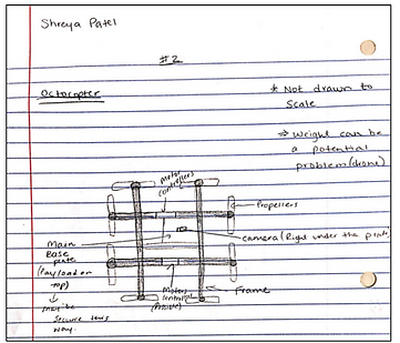
Shreya Patel, Project Scientist and Mathematician
Shreya’s first design concept was a hexacopter designed for stability purposes, with the payload sensors on top of the base plate and the camera directly under the plate. The second concept was an octocopter with similar payload and camera location, but potentially greater lift from the additional rotors (Figure 2.2.2h). The speed controllers and the motors would be located on the framework that connects the base plate to the propellers. This design would require extra material to build a prototype of the drone and therefore scored lower in terms of the business case. The third and final concept was a quadcopter. The payload and camera position remained the same, but a securing mechanism was added around the top of the base plate to stabilize the payload during flight. The team discussion specifically identified the weight of the UAV as a potential problem for the second and third designs in particular, but decided that both the hexacopter and the quadcopter were effective possible designs for addressing the Challenge requirements.
Figure 2.2.2h. Shreya’s conceptual designs.
Kenechi Nkwo, Communications Specialist
Kenechi’s conceptual designs focused mainly on mechanical and computational errors that the UAV might encounter during its flight, such as a power shortage or system communication failure (Figure 2.2.2i). Her first design focused on the position of a payload on the UAV and a potential containment unit for the battery that would enable quick replacement of the drone’s battery. This design would utilize slip grip technology, so that the battery could be easily slipped from containment and a replacement battery could be obtained using the units alternate gripping ability. This process would be completed while the UAV is in flight, assuming that it was carrying a backup battery in anticipation of some power loss or other emergency. Kenechi’s second design further embraced the idea of a battery replacement system which was proposed by fellow team member Maximillian. The second design illustrated a flight mechanism resembling a launch pad that would allow the UAV to board a ramp containing the slip grip fixture, allowing the UAV to remove its present battery, grip onto its replacement, and continue its missions with little no disturbance. The third and final design focused on a location sensor apparatus that would be stationed within the perimeter of the field that the UAV will monitor. If the UAV were to fly out of range of the sensor apparatus detection tools due to a programming error or communication failure, the tool would connect with the drones navigation programming and redirect it to UAS control center.
Figure 2.2.2i. Kenechi’s conceptual designs.
2.2.3 Preliminary Design
The team individually developed designs considering a wide range of components and scenarios for the UAS with a dominant focus on the design of its UAV. Each member examined a specific part of the UAS, such as payload placement , battery swapping mechanisms for the drone, and potential communication systems for the UAV to have with the UAS. Some designs concentrated on battery storage and efficiency, while others addressed the position of the drone’s propellers. Most of the team’s individual designs considered the payload’s placement. The majority of these designs chose to place the payload on top of the base rather than below it in order to provide maximum stability and ease of access. The remainder of the team’s individual designs concentrated on other aspects of the mission such as cattle herding techniques and the implementation of emergency tracking and communication with the drone. Although the final designs produced in this early stage were vastly diverse from each other, the focus of each candidate’s design collectively evaluated the main parts of the UAS (Figure 2.2.3a). This allowed the team to assemble their conceptualized elements into a final design.
Figure 2.2.3a. Design concept decision matrix (selection criteria and scoring based on team votes).
2.2.4 Detailed Design
The team performed significant data analysis to determine the thrust to weight ratio of the aircraft. Acquiring this ratio allowed the project engineers and scientists to understand the required capabilities and strength of the motors. Initially, the team intended to implement the idea of a hexacopter in order to account for its eight pound payload, as the hexacopter was believed to be more stable during flight. However, during the component selection process, it was discovered that the Tigermotor U13 motors selected were powerful enough to effectively lift the payload and airframe weight using only four motors in its design. While a four motor quadcopter proved sufficient, the additional cost and design complexity of a six motor hexacopter was unnecessary. Choosing the rotors for the aircraft did not require much additional analysis. The Tiger Tri Blades were the rotors that the team’s engineers and scientist decided upon, as they were able to connect and work well with the Tigermotors U13.
The team’s final design was sustainable and modular, intended to minimize environmental impact throughout the product life cycle. The design showcases its sustainability through utilizing both carbon fiber and recycled aluminum as the material components of its airframe. The modular entity of the design was created to ease the maintenance of the UAS through the use of interlocking parts. With this characteristic of the design, the systems parts will have the ability to be easily removed, repaired, and replaced, rather than dismantling the UAV in an attempt to change its operation. This will ultimately increase the product life-cycle of the UAV, minimizing waste and creating a foundational design focused on durability and socially-responsible development rather than planned obsolescence. Using the UAV to complete most of the missions as opposed to driving a truck or tractor will also save fuel. Based on initial research, the team found that consumers increasingly value environmental protection and a sustainable design in corporations. Such a design would be a suitable business choice in protecting the team’s image in the real world.
2.2.5 Lessons Learned
The team learned crucial lessons during the design process, including the importance of timely assembly of the team, interactive team work, and time management. These lessons enabled the team to improve upon its weak points and revealed the critical nature of these factors in the process of completing the project. The majority of the team had previously completed last year’s challenge, while the minority of the group joined this year. As of last year, the team had struggled with meeting deadlines and time constraints, which caused the project to be completed just barely in time to meet the extended deadline. This had previously made it difficult to make progress through the design phase because of the team’s lack of unity and communication. This year’s team managed to consolidate each team member’s position before the start of the project, starting the project much earlier and with a better overall understanding of what the project would entail. This was done to prevent a reiteration of last year’s time management issue. The current team also recruited underclassmen in a secondary team to ensure the continuation of the Real World Design Challenge team at ESUMS. This was an essential step, as all of the members of the current team are in their final year of high school. Forming a secondary team this year, allowed the underclassmen to experience the rigors of participation in the Real World Design Challenge in preparation for next year.
Team communication was one of the main aspects of the project that the team has refined from the lessons learned last year. The current team experienced problems at the beginning of the year, when the lack of effective communication strategies led to one or two members completing most of the work. The team realized this error while creating the decision matrix for selecting components of the design and decided that this arrangement could not work as it did not allow for full team participation and collective understanding of the reasoning behind each design decision. All team members needed to be fully knowledgeable regarding the team’s strategy in order to be empowered and competent to make decisions within their own project roles. To resolve this issue, the team assigned specific tasks to every member on the team, dividing up sections for analysis, writing minutes at team meetings and sending periodic reminders from the project manager via email. Using this method, team members’ responsibilities were more clearly established and distributed, and the reason for establishing team roles was more defined, becoming a learning experience for all of the members. Although each member had their own strengths and weaknesses, it was important to learn about all areas of the project in order to write sections in the engineering notebook, make decisions, and answer questions at the presentation.
As the team was better able to adhere to their timeline this year, there was additional time to improve on the engineering notebook after it was initially completed, implementing revisions suggested by the mentors. Despite the team’s early start and attempt to meet all project timeline deadlines, time management was still an area of difficulty for them. Since the team members were divided between two different Engineering Design and Development class periods ( where they had been allowed to work on the challenge), it became difficult to find a time for the entire team to meet. The project manager developed a survey near the beginning of the challenge to determine when each team member was available to meet during the school day or after school. The survey results indicated that there was no time at which all team members could convene within the boundaries of their curricular schedules and other extracurricular activities.The team decided to meet regularly during the class period in which the most team members were available, but this setback increased the difficulty of team communication and remaining consistent with the pre-established timeline. Falling slightly behind in the timeline put additional pressure on the team to realign themselves with the due dates on the timeline in order to be on schedule to submit their notebook to their mentors for review prior to the official challenge deadline.
From the lessons that the team learned this year, the team would suggest that the upcoming RWDC team for next year to refer to this document and additional information that will be provided before beginning the challenge. The goal is to make the transition from the team to team smoother and more effective in maintaining the RWDC program at ESUMS. As mentioned earlier in this section, the current team recruited underclassmen to continue the RWDC next year. Therefore, the team would suggest that these underclassmen either finalize the team composition by the end of this year or the very beginning of the next school year. In addition to this, the secondary team should plan and organize the meetings and the timeline for the competition ideally no later than October. This will allow the members to stay on track for the notebook deadline and also establish a strong start to the competition.
2.2.6 Project Plan Updates and Modifications
The team created a timeline for this project based on their experience from previous years participating in the Real World Design Challenge. They understood that the preliminary design work needed to be completed quickly and in sequential order with full team participation to ensure that the design accurately reflected a rigorous component selection process. The team members had to simultaneously read through the background material, conduct research on existing UAVs, and brainstorm effective and innovative designs that addressed the Challenge requirements. Once the research phase was completed, the team had to finalize the designs and prepare them for presentation. During the first presentation of design concepts to other students in the Engineering Design and Development class, it was discovered that many of the designs could not be adequately explained to other group members or the general public. Therefore, the preliminary design activities and timeline were adjusted to allow the team members more time to fully develop their envisioned designs. Although this process extended the time spent on the general project plan, it also ultimately enabled the team to have a solid candidate design from each member. Approximately three design iterations were developed by each team member, and then the complete design went through an additional three iterations before being finalized.
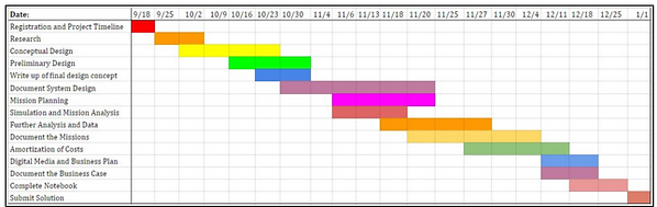
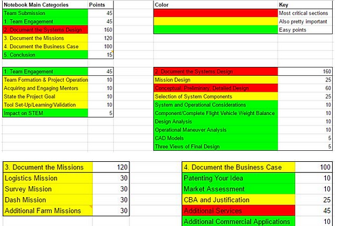
To stay on track with the challenge timeline, the team created a Gantt chart (Figure 2.2.6a) to maintain consistent progression through the tasks. This initial Gantt chart was updated several times to account for delays such as college application deadlines, school breaks, and exams. Based on one of the mentor's’ suggestions, the team broke down the sections of the RWDC rubric by number of points in order to determine weighting and priority (Figure 2.2.6b). This was extremely helpful in deciding which sections should receive a larger portion of the team’s time and effort.
Figure 2.2.6a. Initial Gantt chart.
Figure 2.2.6b. RWDC rubric breakdown by weighting and priority.
2.3 Selection of System Components
2.3.1 Payload Selection
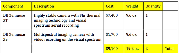
The broader focus of this challenge in relation to the three required missions and the three additional missions defined by the team makes the payload a critical component of the air vehicle, as it is essential for carrying out the designated functions of the UAV. The team closely examined the camera options provided in the Real World Design Challenge catalog, but ultimately decided that none of them exhibited the level of durability, quality, and versatility of function necessary to perform six independent missions. Therefore, after researching a variety of different camera options, the team’s decision matrix process (Figure 2.3.1a) resulted in the selection of the Zenmuse XT, a DJI thermal imaging camera. The DJI camera has excellent stabilization from a 3-axis brushless gimbal and takes high-quality video footage with a frame rate of 25-30 Hz. Most notably, the Zenmuse XT has greater flexibility of use as it is sold commercially in a wide range of sizes and lens models to accommodate different needs for situational awareness, magnitude, spot size, and area coverage, allowing us to select individual customizable features based on our missions choices (DJI, 2016).
Figure 2.3.1a. Camera decision matrix selections. ***Note: Cameras considered in decision matrix were finalists in team discussions, identified as contenders through initial research. Qualitative rankings were determined through voting by team members and quantitative rankings by numerical sequential order (i.e. highest price = 1, lowest price = 5).***
Currently used for UAV applications in building surveying and firefighting, the Zenmuse XT captures both thermal imaging and visual spectrum footage and can be purchased from Flir for an average of $7,400 (price varies with location and exporting options). This makes it comparable in price to the RWDC catalog’s X1000 and X5000 and far less expensive than the X3000 and X4000, which cost $17,000 and $20,000 respectively. The team’s cost analysis determined that the added features in the catalog’s most expensive options were not sufficient to justify the impact of the added cost on the objective function and business case. The Zenmuse XT’s wide range of capabilities made it the best option for performing diverse mission assignments, as it is capable of generating topographic thermal data for subsequent analysis in programs such as ArcGIS, QGIS, and R and also stores visual images on an SD card for future file transfer and storage. The thermal imaging function is necessary for moisture detection in the survey mission, and the visual spectrum images will be used in multiple missions, primarily for 3D image-stitch advanced options and livestock monitoring. This diversification of functionality and cost-benefit criteria makes it a competent and cost-effective tool for performing navigation and data collection functions across multiple missions.
However, after further research into the capabilities of the Zenmuse XT camera, the team engineers determined that it could not record video footage on the visual spectrum, and so an additional Zenmuse X5 camera was necessary to fulfill all mission requirements and collect video data. This camera was only $1,700 and provided extensive extra functionality, thereby making it worth the additional cost.
In previous years, the team included additional sensors such as the microcontroller and multiplexer in the payload section (Figure 2.3.1b). However, this year, it was decided that these components should instead be included in the selection for the air vehicle element, based on their location in the catalog. The camera is the standard payload for most conventional drone missions and will require special attachment fixtures and stability considerations, meriting individual analysis in this section. Despite this logistical separation, the supplemental sensors will be accounted for in calculations of payload weight for the objective function, as this may vary between missions. The team determined that an arrangement of modular, interchangeable components that can be added for each mission is preferable for maintenance and repair to a solid and immutable design.
Figure 2.3.1b. Payload cost matrix.
2.3.2 Air Vehicle Element Selection
The team’s design was originally based on the multirotor option from the Real World Design Challenge catalog. Many of the conceptual designs were created with the multirotor option in mind, as it most closely resembled the drones that team members had previously built in their engineering classes. Initial designs were primarily hexacopters with six rotors as depicted in the catalog. The project engineers’ analysis of the power capabilities of a selection of motors indicated that six motors would be necessary to lift the calculated payload weight and fulfill all mission requirements. However, further research and comparison of motor capacities revealed that the 85 kV Tigermotor U13 was sufficiently powerful to meet all requirements with only four motors in a quadcopter arrangement. This saves materials and cost, while meeting the challenge requirements with greater mechanical efficiency. The motor selection process is illustrated in the comparison matrix below (Figure 2.3.2a).
Figure 2.3.2a. Motor selection process comparison matrix.
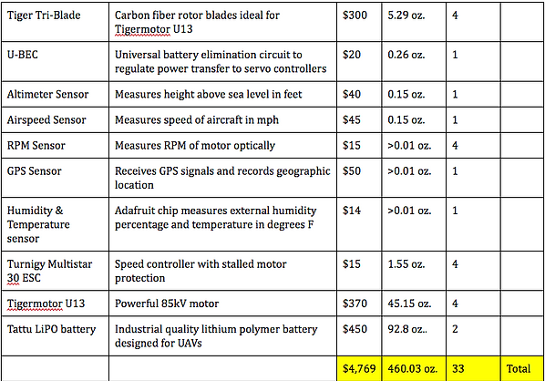
The U13 motor is ideally suited for the carbon fiber Tiger Tri-Blades, each weighing 5.29 oz. and costing $300. These blades are rigid, lightweight, well-balanced, and able to cope with the stresses that the aircraft will face while in flight, as determined by the flight analysis calculations. They are expensive, but the higher cost is made up for a great improvement in quality and durability, so these blades will need to be replaced far less frequently than less costly alternatives. In order to mitigate the effects of this higher cost, the team will be testing all prototypes with less advanced rotor blades, both the drone that the team is currently building and any future developmental models. This will remove the risk of purchasing the advanced blades only to discover a deeper design flaw and will also validate the team’s stress and strain analysis, as if the less durable trial blades function effectively throughout test missions, the Tiger Tri-Blades most certainly will as well.
The airframe for the UAV was adapted from the multirotor design presented in the RWDC catalog, but the original hexacopter was modified to be a quadcopter with four more powerful motors. The $900 cost for this item as noted in the table below (Figure 2.3.2b) was estimated based on the current price of the carbon fiber and recycled aluminum materials that will be primarily used in its construction. This value vary based on the availability of a recycled aluminum market, the rise and fall of rare materials prices, and the country in which the drone is being manufactured and sold.
Other notable components included in the air vehicle elements selection include the universal battery elimination circuit, Turnigy Multistar 30 ESC speed controller, and Tattu Solutions lithium polymer battery. These were either transferred directly from the RWDC catalog (U-BEC) or identified through online research as a better, more cost-effective alternative to the options offered in the catalog (speed controller and battery). In order to complete all missions, many sensors were needed and are detailed in the table below. These do not add significantly to the weight of the payload and have only a small additional cost, but can generate large quantities of data, making the data analytics service discussed in section 2.3.5 more valuable to customers. It is possible that in future design iterations, customers would have the option to choose which sensors they would like to include for a small discount, depending on their individualized needs.
Figure 2.3.2b. Aerial vehicle component cost comparison matrix.
2.3.3 Command, Control, and Communications (C3) Selection
A flexible and adaptable command, control, and communications system is critical in this instance to allow the operator to best utilize the wide range of information that will be made available by the differing functions of the UAV (Figure 2.3.3a). In some missions, it may be advantageous in terms of ease of use and cost to store collected data in the aerial vehicle itself for future transfer, while in other missions, direct transmission of data to the ground control station would be more advantageous. Therefore, the UAV will be equipped with a ground-based 900 MHz patch antenna to improve its communication range, so that data can be transmitted to the ground control station and analyzed in real-time using the High Power Video System and radio for wireless transmission and receipt of camera videos. This improves the ease with which the farmer can receive important information, particularly during missions like the monitoring of livestock and weather changes, during which the farmer must make timely decision such as moving livestock to a new location or intercepting a straying animal.
Figure 2.3.3a. C3 component cost selection matrix.
2.3.4 Support Equipment Selection
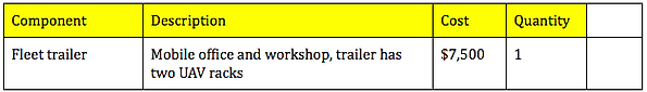
The support equipment required by the UAS included equipment to transport the UAV to and from the operation site (Figure 2.3.4). After careful consideration of all potential impacts, the team decided that many of the features of the trailers listed in the support equipment catalog subsection of the Detailed Background document were unnecessary for the challenge objectives, particularly considering their high cost and the price and environmental impact of the fuel that would be expended by such a large vehicle. The team therefore decided to use the Fleet trailer option, as it provides sufficient room for all operations and includes UAV racks of the requisite size. The team also considered the need for a vehicle to tow the trailer, and chose a 2012 Chevrolet Colorado pickup truck. It costs significantly less than most pickups, only $15,000 compared to much more expensive competitors in the range of $30-40,000, while still providing enough power to haul the trailer and UAS. It also has enough cabin space for personnel and other miscellaneous items. This vehicle would be retained by the company to be operated by trained personnel during farm operations and transportation of equipment
Figure 2.3.4a. Support equipment component cost comparison matrix.
2.3.5 Human Resource Selection
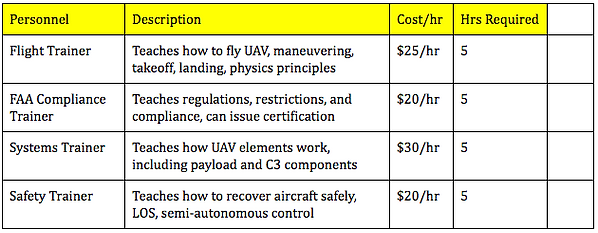
The training course necessary to provide the farmer with full knowledge, certification, and experience in operating the UAS requires four certified trainers to guarantee adequate preparation. Operating an unmanned aerial vehicle can be extremely complex with great potential for error, and this training will minimize accidents, safety hazards, and company liability from regulatory infringement, as well as preparing the customer to obtain the greatest benefit from the UAS in fulfilling their agricultural needs. Therefore, the company will provide a 20-hour training course for a cost of $500, as the sum of the per hour cost of hiring the trainers ($475) plus a small processing and logistics fee ($25). The flight trainer, FAA compliance trainer, systems trainer, and safety trainer will each instruct for a five-hour block, and farmers will have the option of taking the training course for three days continuously, or for one day per week for five weeks, offering greater flexibility and accommodation for different work schedules.
In addition to the training personnel, the company will also hire a maintenance and repair technician to provide repairs for the UAV. This technician will be able to repair damage to physical components and replace parts, for a fee of $25 per hour. The team’s research has shown that these are the parts of the drone most likely to warrant repair, and in the unlikely event of a failure to the C3 or electronics systems, an outside contractor could be brought in to provide more specialized repairs. Estimates of maintenance fees for similar companies indicate that there will be an expected yearly total of 10 maintenance hours required for a total annual expenditure of $250 on maintenance personnel. The maintenance and repair technician hired by the company will be of particular importance to the company’s goals of sustainability and extended product life cycle. The UAV’s modular design and removeable parts will allow the technician to replace or repair individual components in the event of a malfunction, rather than repairing the entire device, thus extending the product’s lifespan and decreasing waste. For this reason - and because maintenance profits are prohibited by the challenge guidelines - the company will charge a flat fee for the technician’s salary and the cost of new parts, making no profit from repairs.
Finally, the company will require a data analyst to analyze, consolidate, and communicate data collected by the UAV during its missions, particularly the moisture detection survey mission and 3D imaging additional mission. This analytics service will be offered to farmers for an additional fee, an extra marketing point to increase the attractiveness of the service and product to potential buyers. This service will extend to functions far beyond what is taught to farmers in the basic C3 training course offered by the systems trainer, encompassing high-performance processing of images to create 3D models of land formations and calculations surrounding moisture content data based on the Topographic Wetness Index and other similar benchmarks of crop moisture flow. The data analyst must be proficient in several different softwares, primarily Autodesk’s photogrammetry application, ArcGIS, QGIS, and other methods of higher level processing and interpretation. They will be hired for a rate of $35/hr, and will likely need approximately 7 hours of analysis per mission. This is an average estimate, as some missions will require longer periods of analysis while others will require far fewer hours to complete the analysis, if any time at all is needed.
While the salaries for these personnel do add to the overhead cost of the company, as well as the per unit/mission cost, these human resources play vital roles in the success of the mission. Some individuals, like the four trainers are necessary to meeting FAA requirements and ensuring that the customer is adequately prepared to operate complex machinery. Paying this cost upfront minimizes the risk of potential future costs or damages to brand image and reputation arising from litigation or other legal issues. The technician and data analyst, while not essential to the technical and regulatory aspects of the UAS, make the company more competitive as many similar drone manufacturers offer such services. These additional customer service options are critical to maintaining market share and staying ahead of competitors.
Figure 2.3.5a. Human resource element cost comparison matrix.
2.4 System and Operational Considerations
Perhaps the most prominent tradeoff inherent in the design was the direct relationship between the quality and effectiveness of a component and its cost. This was a particularly difficult proportion to balance, as increasing the effectiveness of a particular motor or sensor naturally increased the speed or efficiency with which a particular mission could be completed, increasing f1-f4 of the objective function. However, this would simultaneously add to the total expenses value, lowering f5. Therefore, throughout the component selection process, the team tried to select components that had the greatest value for the lowest cost. Some, like the Tigermotors and Tiger Tri-Blades were quite expensive by necessity, but were included as they drastically increased the UAV’s ability to perform adequately, staying aloft for the required time in the survey mission and flying sufficiently quickly during the dash mission. Others, like the humidity and temperature sensors, greatly increased the multipurpose functionality of the system without increasing the total system cost by any significant degree.
As the challenge documentation stated, the team was required to examine the FAA regulations for Small Unmanned Aircraft. Many of these regulations were already incorporated into the constraints set by the Real World Design Challenge, such as the 55 lb limit for the weight of the UAV. The team first identified and analyzed the pertinent regulations, then ensured that the design met the FAA operational limitations as well as the constraints imposed by the product’s target markets. The regulations included limitations such as prohibiting operations to be conducted from moving aircraft or during nighttime, an important consideration during the mission design phase. These constraints were already met in the initial designs, because farmers, as the project target consumers, do not conduct operations from aircraft and typically do all work during the daytime. When the team identified these factors as addressing the FAA requirements, they were able to ascertain that most of the FAA (part 107) regulations were met by the nature of the challenge as well as the team’s consumer targets. This was beneficial because the team was able to work freely on designs and component selections within the guidelines of the FAA regulations. The team was able to explore a wide range of ideas while still meeting the constraints of the FAA regulations.
The final values of the five sections of the objective function are as follows: f1 = 0.9110, f2 = 0.6000, f3 = 0.8644, f4 = 0.7388, f5 = 0.1423. The average of these values gives the final objective function value of 0.6513. The logistics mission and dash mission were the highest optimizations of their respective values in the objective function, followed by the additional missions value, then the survey mission. The f5 value for revenue, expenses, and profits is the lowest of the values, but cannot be easily compared to the missions as it measures a vastly different criteria. This is emblematic of a larger trend in the design process that placed a greater emphasis on quality and effectiveness than on increasing profits. However, the outcome of the business plan and the calculator (attached separately) shows that the solution is still commercially viable.
2.5 Component and Complete Flight Vehicle Weight and Balance
Our microcontroller allows for active and preset thrust adjustment through the ESC’s. Since our quadcopter is symmetrical in all directions, we can arrange the ESC’s and other components radially to avoid having to account for them. The low weight electronics though, are individual components and cannot be grouped in fours, so they receive their own central housing. The batteries are the most heavy non-centered component, and their position towards the rear of the aircraft is only symmetrical on one axis, meaning the rear motors need a little bit more thrust to balance, but the microcontroller is able to account for this as a baseline coefficient. The pixhawk also uses the onboard gyro sensor to correct for unwanted positional changes to the aircraft, and will compensate for any random imbalance caused by possible worst-case scenarios, such as a sudden imbalance due to the breach of a component housing.
Figure 2.5a. Component grouping abstract.
2.6 Design Analysis
There were four major categories of constraints that had to be dealt with when designing the UAS: flight, regulation, cost, and environment. The flight constraints analysis is covered in 2.7, but the decisions regarding the other subjects were not as relevant to the maneuvers. The topic of regulations specifically refers to the FAA small unmanned aircraft (part 107) legal guidelines. The unmanned aircraft’s weight without payload is approximately 30.4 lbs, with payloads ranging from 0.59 to 8.59 for each minimum requirement mission. Based on the maximum thrust of the motors though, the system can attain up to 115 lbs of thrust, which is sufficient to meet the overhead thrust requirements of the maximum 55 lb weight. In other words, if a mission allows for more payload than what is listed, the quadcopter is capable of lifting and maneuvering with a full 55 lb weight. To calculate the maximum additional payload for the mission with, simply subtract the mission payload and gross takeoff weight (30.4 lbs) from 55 lbs. Because the aircraft is capable of lifting above the limit, it was necessary to cover the legal implications regarding overloading the airframe. The microcontroller that was selected allows the team to monitor the ESC’s and the accelerometer to prevent the drone from taking off if it is unable to gain vertical acceleration with approximately 13 amps of current draw from each motor. This translates to just under 55 lbs of thrust, meaning that the aircraft should give a warning if its weight is too high. It is the farmer’s legal decision to heed this notice, which protects the system ultimately. This same microcontroller is also able to use GPS data to accurately determine elevation, causing the motors to max out at 50% throttle (or equivalent hover) when approaching the 400 foot legal height limit. The airspeed sensor is used to limit the airspeed to the legal 87 knots, however it is impossible for the aircraft to reach this speed under its own power in neutral winds due to drag. This system exists as a failsafe should the wind allow the aircraft to gain excessive speed.
Environmental factors were also a concern when designing the system, especially regarding weather conditions. Although the system was designed around a specific chosen location, it was important to ensure that it would be able to operate identically anywhere in the world to increase the range of our target markets. In order to be operable in cold weather, every single component chosen has a way of generating its own heat, even the ESC’s. Although the drone wouldn’t be used as often during these times as crops would’ve already been harvested in the winter, the aircraft’s additional missions provide additional year-round functionality which must be accounted for. As for overheating, the datasheets of each non-catalog component have been thoroughly checked to account for this. Even the motors have been tested in real life with a thermal camera to run at longer durations that even this our design requires and show no excessive heat generation under full throttle. However, in the event that the drone is flying in conditions with excessive temperature, there is an onboard temperature sensor which will trigger the return to home function of the microcontroller if necessary. But temperature wasn’t the only challenge of this category, wind speed and local elevation also had to be accounted for. The motors are powerful enough to provide similar performance for the minimum requirement missions at up to 7500 feet of elevation, with the assumption that as elevation increases, the additional possible payload discussed in the legal section decreases. This overhead also allows the drone to hover in winds approaching its maximum airspeed, with the maximum airspeed decreasing into a headwind , and increasing up to 85 knots while travelling downwind.
The last major design factor was certainly cost. The most expensive parts of the system are the motors, and payload sensors. It was necessary to stay significantly less expensive than competing drone platforms with similar payload capabilities, and therefore the team chose a lesser amount of larger, more efficient motors to accomplish this. While this did come at the cost of sacrificing potential redundancy, it was necessary to keep the cost low enough to be profitable. The possible benefit of adding two more batteries to double the capacity whilst increasing the gross takeoff weight was also considered, but the team eventually decided against doing so, as the minimum requirement missions were already met by the two battery setup, and the additional cost was not justified. The numbers comparing the flight times of the battery numbers is found below, in section 2.7.
2.7 Operational Maneuver Analysis
The first constraint considered in the operational maneuver analysis calculations was flight time. From the earliest conceptual stages of the design, the battery life was determined to be one of the limiting factors of the design. By following the mission constraints, the team was able to design a UAV capable of completing every single mission initially envisioned. The design eventually selected has some additional advantages demonstrated in calculations of its flight time and airspeed, as a quadcopter has no particular heading or necessary flight direction as long as its camera can move independently from the chassis. Because of this, the notion of a turning radius that would complicate the flight pattern of a fixed-wing aircraft does not exist on a quadcopter, which can stop in place and perform a zero-degree turn or simply move over without turning the chassis. Thus, destination missions and survey missions require no compensation for turn radius.
With the selected battery component, maximum flight time was determined for each minimum-requirement mission to prove that the flight times were above the required constraints. Then, the ideal airspeed and camera footprint were used to calculate the times for the survey mission.
Duration Calculations:
Possible Configurations of 22A 22.2v batteries
2s 1p (As calculated above) (30.4 lbs)
2s 2p (+11.5 lbs and ~$1000 but 2x the capacity) (41.9 lbs) → still within limits w/payload
Requirements:
44.4v
30.4lb hover for 2s1p (7.6 lbs per motor)
32.4 lb hover for 2s1p w/ 2 lb payload (8.1 lbs per motor)
38.4 lb hover for 2s1p w/ 8 lb payload (9.6 lbs per motor)
41.9 lb hover for 2s2p (10.475 lbs per motor)
43.9 lb hover for 2s2p w/ 2 lb payload (11 lbs per motor)
49.9 lb hover for 2s2p w/ 8 lb payload (12.5 lbs per motor)
****Note that any configuration above 2s2p would likely exceed the 55 lb weight limit and consequently was not calculated here.
Flight Times:
30.4 lb Hover: 7A+0.5 avionics
Total: 28.5A
Duration 2s1p hover: ~46 minutes, no payload
32.4 lb Hover: 7.5A +0.5 avionics
Total: 30.5 A
Duration 2s1p hover: ~43 minutes, 2 lb payload
38.4 lb Hover: 9.5A +0.5 avionics
Total: 38.5 A
Duration 2s1p hover: ~34 minutes, 8 lb payload
41.9 lb Hover: 10.5A+ 0.5 avionics
Total: 42.5 A
Duration 2s2p hover: ~62 minutes, no payload
43.9 lb hover: 11.5A +0.5 avionics
Total: 46.5 A
Duration 2s2p hover: ~57 minutes, 2 lb payload
49.9 lb hover: 13.2A +0.5 avionics
Total: 53.3 A
Duration 2s2p hover: ~50 minutes 8 lb payload
Figure 2.7a. Amps versus thrust graph and calculations.
Survey Maneuvers:
Using the specifications of the camera:
Sensor Width: 6.12 mm
Sensor Height: 4.62 mm
Focal Length: 20 mm
Maximum Height: 400 Feet
Gimbal Angle: 30 Degrees
There is a maximum camera footprint of (161.15 feet)*(123.75 feet), meaning that for a standard row pattern flight path, an image must be taken at least every 123.75 feet, and the row width will be 161.15 feet. By dividing 0.25 miles (1320 feet) by 161.15 feet, it can be determined that there will need to be nine full rows of 1320 feet, connected by eight sideways maneuvers of 161.15 feet, plus the calculations for maximum rate of ascent, and an additional 1867 feet assuming the UAv must return to the origin of takeoff. The total necessary distance to travel horizontally at altitude for the second mission is 15036.2 feet or 2.85 miles. To determine if this is possible with the selected battery, it is necessary to know the cruise speed, ascent speed, and power draw when cruising.
This represents the maximum possible airspeed.
Final Max Airspeed is 65 knots. The survey mission flies at 30 knots to capture e
2.8 CAD models
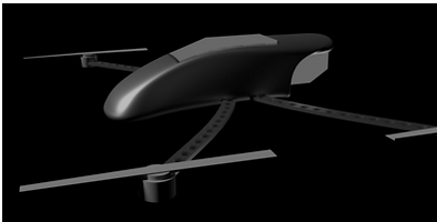
Figure 2.8a. CAD model with realistic render.
Figure 2.8b. CAD model with blueprint render.
2.9 Three View of Final Design
Figure 2.9a. Three views of final unmanned system design.
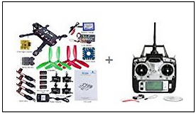
In addition to the CAD models shown above, the team has decided to construct a physical prototype and model of the final UAV design. Due to a limited budget and time constraints, this model will be scaled-down from the proposed full version, using less costly materials, batteries, motors, and rotor blades. It will also have somewhat diminished capabilities in speed and payload capacity so that it can be tested using Dr. Oparaocha’s FAA license. However, this scaled-down prototype will enable the team to test the systems design and theory of operation before manufacturing a full version. This model will also serve as a realistic visual aid for use in promotional materials and explaining the UAV’s functions to potential customers. Using funding obtained from the PTO, the team has ordered a set of standard parts in accordance with the final design and an accompanying transmitter (Figure 2.9b). These parts will be supplemented with items already owned by the engineering department and the robotics team.
Figure 2.9b. Drone parts for model/prototype UAV.